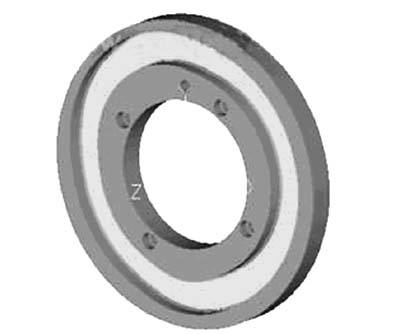
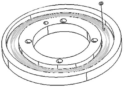
Click the TooLpaths toolpath creation button, select the Contour 2D contour toolpath, select the series as shown in Figure 2 and confirm, the software pops up the machining parameter setting dialog box, select the Φ10mm tool, and set the contour parameters. 3. Get the interpolation point The contour tool path is generated and post-processed to obtain the machining program of the tool center on the contour, so that the interpolation points on the central motion trajectory of nearly 400 cam rollers are obtained. Using the interpolation points obtained by the above method, we compiled the NC program and tried it on the VCP1000 high-speed milling machine. A new problem appeared: As can be seen from Figure 1, the groove width of the cam groove is Φ22+0.05. If it is directly processed with Φ22 tool, Unable to meet drawing accuracy requirements. Therefore, our original machining plan is to use the Φ16 machine to clamp the rough milling cavity, and then use the Φ16 side fine-edge milling cutter and use the radius compensation function of the numerical control device to finish the cam track surface. However, because the number of coordinate points is too dense, the tool compensation function cannot be used, and the machine refuses to execute the program, so the machining cannot continue. Second, the problem solving process Through the powerful modeling and processing functions of I-DEAS software, the processing problems of cam grooves can be effectively solved. The specific process is as follows: 1. Establish a basic entity Start I-DEAS, enter the software modeling module, select the graphic button in the task command menu area, draw Φ220 circle in the default drawing plane of the software, select the stretching command button, click Φ220 circle as the section stretching 30mm, generate as shown in Figure 2. The basic entity shown. 2. Establish a three-dimensional model of the cam groove Click the task command menu, select the A plane shown in Figure 2 as the drawing plane, establish the reference coordinate system at the center of the Φ220 circle on the drawing plane, select the reference point command button, and describe the 36 coordinate points of the center track of the cam roller. Input, get 36 reference points, click the spline curve drawing button, connect 36 reference points, establish the cam roller center trajectory, select the offset function button to offset this trajectory to each side by 11mm, click on the entity Stretching the feature, selecting the two curves obtained by the offset as the section, cutting the material on the base body to obtain the cam groove feature, and then creating other features of the workpiece by a similar method, and the resulting workpiece solid model is shown in FIG. Figure 3 generated solid model 3. Establish cam groove roughing tool path Select the Generative Machining task in the task list area in the upper right corner of the I-DEAS software window. The software enters the generative machining environment, the function buttons in the task icon menu area will change, and the planar cam groove workpieces created in the modeling module will be brought directly into the processing module. After the machining task is established, the cam groove solid model is selected to establish the machining object. Click the Create New Action icon button to open the Operation Selection dialog box, select the machining method, and click the Create button to open the Operation Settings dialog box. Through the setting of each item, the tool path for finally obtaining the cam groove cavity roughing is shown in Fig. 4. Figure 4 Roughing tool path Previous page next page 
