1. Body structure analysis process <br> <br> the body is a cylinder, the processing requirements of several eccentric hole in the left end surface of the valve body radially distributed processing of the bore in the axial groove, the Thread forming to dimensional requirements, using special processes to achieve surface quality requirements. The valve body was machined using a CA6140 horizontal lathe. The main processing of 5 forming holes, the remaining unnumbered holes due to processing accuracy and surface quality requirements are not high, can be processed to the requirements using ordinary drilling process. For example, the R a of the holes No. 1, 3, 4, and 5 is 1.6 μm, and the R a of the No. 2 hole is 0.4 μm, and the polishing method must be used. As shown in Fig. 1, the five holes have higher geometric tolerances and dimensional tolerances, the highest position is 0.05 mm, the highest cylindricity is 0.033 mm, and the lowest surface roughness value R a is 0.4 μm. Since the position of the four eccentric holes in the five holes is irregular with respect to the center reference hole 2, and the mutual asymmetry, coupled with the difficulty of processing, it is necessary to use the eccentric indexing rotary device for processing. Previous page next page
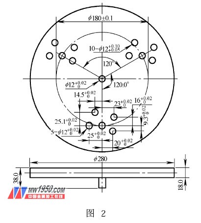
2. Design of eccentric indexing rotary fixture (1) The positioning scheme is designed to be fixed on the CA6140 horizontal lathe main shaft by the eccentric indexing disc (as shown in Fig. 2). The indexing disc has a uniform distribution of the third group. Eccentric positioning of the mounting holes, the position of the five eccentric holes in each group is required to be the same as the size of the valve body parts. The valve body part is loaded into the clamp body, and five positioning holes for eccentric holes are drilled in advance on the right end surface of the valve body for positioning, and the positions opposite to the left-end machining forming holes are opposite to each other. By positioning the five pre-holes on the workpiece and on the centering convex axis of the indexing plate, the axes of the eccentric holes coincide with the axis of the lathe spindle.
(2) Clamping scheme design clips are specifically clamped and clamped in the indexing holes by bolts and nuts on the discs. The workpieces are clamped in the clips with a small clearance fit and four screws on the left. 