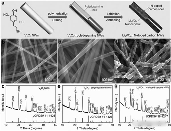
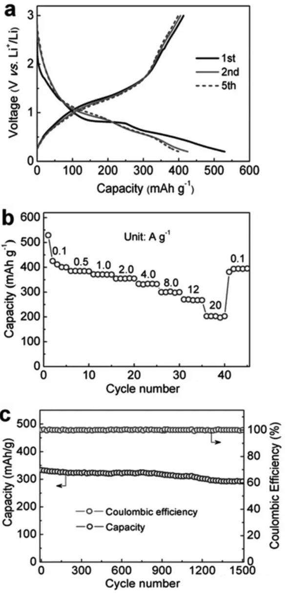
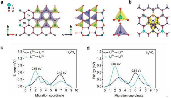
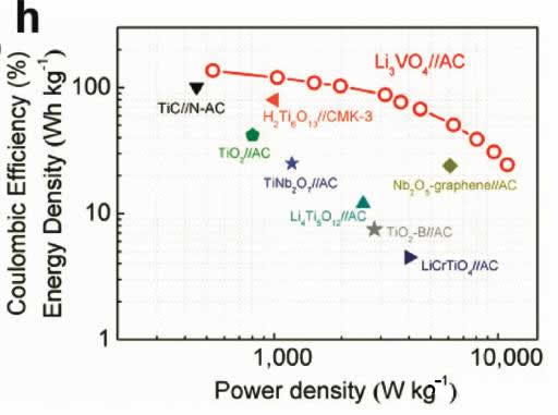
Supercapacitors are emerging energy storage components in recent years. Their outstanding features are high power density and long cycle life, but their energy density is very low (less than 10Wh/kg), and lithium ion batteries have high energy density (over 200Wh/kg). ), but the power performance is poor, and the cycle performance is not as good as a super capacitor. In the field of electric vehicles we need both high energy density (longer cruising range), high power density (faster charging speed), and longer cycle life (longer battery life), so a combination Energy storage components with the advantages of supercapacitors and lithium-ion batteries have emerged: lithium-ion capacitors. In general, a lithium ion capacitor is composed of a positive electrode of a super capacitor and a negative electrode of a lithium ion battery, and the electrodes on both sides comply with respective working principles, thereby achieving the purpose of greatly increasing the energy density and power density of the capacitor. Recently, China University of Science and Technology, Chinese Academy of Sciences and Germany's Max Planck Solid Research Institute jointly developed a high-energy lithium-ion battery container based on Li3VO4/N-doped graphite nanowires. With a power density of 532 W/kg, the capacitor has a high energy density. 136.4Wh/kg, the results have been published in the latest issue of advanced material. Compared with Li4Ti5O12, TiO2, H2Ti6O13 and other materials, Li3VO4 material has the characteristics of low insertion voltage (0.2-1.0V), high capacity (394mAh/g), and advantages of small changes in structure and volume during charge and discharge. This makes it very suitable as a lithium ion capacitor anode material, but the conductivity of Li3VO4 material is very low (<10-10S/cm), which also greatly limits the rate of Li + intercalation reaction, limiting the lithium ion capacitor The power density. Carbon coating and nanocrystallization are commonly used methods to improve the conductivity of materials. In order to improve the conductivity of Li3VO4 material, Liifa Shen synthesized Li3VO4/N-doped graphite composite nanowires with pea pod structure using the method shown in the above figure. This structure overcomes the disadvantage of low conductivity of Li3VO4 material. With high Li+ and electron diffusion rates. With this material as the negative electrode, the carbon material is a positive electrode combined to become a lithium ion capacitor, and the specific energy can reach 136.4 Wh/kg (at a power density of 532 W/kg). The lithium insertion reaction equation of Li3VO4 material is shown in the figure below. In the cyclic voltammetry test, the reduction current peaks appear at 0.73V and 0.53V, respectively, and the oxidation current peaks appear at 0.76V and 1.34V, respectively. It is worth noting that except for the first cycle, the curves of the other several cycles overlap completely. The electrochemical performance test results of the Li3VO4 material are shown in the figure below. The charge and discharge curve is shown in Figure a. The initial discharge capacity and charge capacity are 529mAh/g and 413mAh/g, respectively. Figure b shows the rate performance test. You can see from the test results. At a current density of 1, 2, 4 and 8 A/g, the capacity of the material can reach 372, 354, 333 and 300 mAh/g. At a high current density of 12 and 20 A/g, the discharge capacity of the material remains Up to 271 and 203 mAh/g, indicating that the material has very good rate performance. From the cycle performance of Figure c, we can see that the material has very good cycle performance. Under the current density of 320mAh/g, the capacity retention rate of the cycle 500 times can reach 96%, and the capacity retention rate of the cycle 1500 times can reach 88%. Laifa Shen believes that the excellent electrochemical performance of Li3VO4/N-doped graphite composite nanowires may benefit from its unique structure. The internal N-doped graphite forms a very good electronically conductive network inside the material, and the externally coated graphite The material can well inhibit the agglomeration and growth of the Li3VO4 material and maintain its nanostructure, thus greatly reducing the diffusion distance of Li+ and e-, thereby improving the material's rate performance and cycle life. According to the first-degree calculations, LaifaShen believes that in Li3VO4 crystals, Li+ can be embedded in the 2a and 4b sites, but is more inclined to the 2a site. The potential barriers for Li+ diffusion to the 2a and 4b sites are shown in Figures c and d. It can be seen that the barrier to Li+ entry to 2a is significantly lower than the diffusion to 4b, while we also follow the material As the Li+ concentration increases, the barrier to Li+ diffusion also increases. Calculations also show that even if two Li+s are embedded in each cell of the Li3VO4 crystal, the volumetric expansion is only 4%, which also ensures the good cycling performance of the Li3VO4 material. Lithium ion capacitors made of Li3VO4 material are shown in the figure below. The positive electrode is activated carbon and the negative electrode is Li3VO4 material. The working voltage of this capacitor is up to 4.2V. When the charging voltage is increased from 3.0V to 4.0V, the specific energy of the capacitor can be increased from 25.5Wh/kg to 120.2Wh/kg, and the energy density can be increased by as much as 470%. The relationship between the power density and the energy density of the capacitor is shown in the figure below. With a power density of 532 W/kg, the energy density can reach 136.4 Wh/kg. Even at a power density of 11020 W/kg, the specific energy can still reach 24.4 Wh. /kg, which is much higher than other types of lithium ion capacitors. The relationship between the power density and the energy density of the capacitor is shown in the figure below. With a power density of 532 W/kg, the energy density can reach 136.4 Wh/kg. Even at a power density of 11020 W/kg, the specific energy can still reach 24.4 Wh. /kg, which is much higher than other types of lithium ion capacitors. A Hose Clamp or Hose Clip is a device used to attach and seal a hose onto a fitting such as a barb or nipple. Many types are available, including American hose clamp, German hose clip, British hose clamp , Screw/band (Worm Gear) clamps, t-bolt clamp, Spring clamps, Wire clamps, Ear Clamp and so on.
Hose clamps are frequently used for things other than their intended use, and are often used as a more permanent version of duct tape wherever a tightening band around something would be useful. The screw band type in particular is very strong, and is used for non-plumbing purposes far more than the other types. These clamps can be found doing everything from mounting signs to holding together emergency (or otherwise) home repairs.
Hose clamp Sealing and mechanical strength
One of the fundamental goals of most hose clamps is to ensure a tight seal between the hose and the barb, preventing the working fluid from escaping. To this goal, they are designed to provide even pressure on all sides, with no gaps. An example of this would be wire clamps. An obvious design would seem to be simply having a wire around the hose, one end attached to a nut, and the other end to the screw, and when tightened, pulling the ends of the wire towards each other. However, this will leave a gap where no pressure is applied (underneath the screw), and cause a leak. To combat this, the more complicated and weaker design of having the ends overlap and then be pushed apart from each other is used, as this ensures pressure around the entire circumference of the hose.
Hose Clamp Hose Clamp,Stainless Steel Hose Clamps,Hose Clip,Pipe Clamps SHIJIAZHUANG TOPA TRADING CO., LTD. , https://www.topahydraulic.com


Hose clamps are typically limited to moderate pressures, such as those found in automotive and home applications. At high pressures, especially with large hose sizes, the clamp would have to be unwieldy to be able to withstand the forces expanding it without allowing the hose to slide off the barb or a leak to form. For these high pressure applications, compression fittings, thick crimp fittings, or other designs are normally used.
Hose clamp Uses and applications