We are putting most of our resource and effort into Ratchet Straps and their accessories.
Besides ratchet buckle,straps,what else is missing?
Yes,End Fittings,so here are what we strongly suggest-flat Hooks.
We have various surface treatments for your options,like black electrophoretic plating and galvanizing.
And yet,it's easier than other hooks that for flat hooks,you can make your LOGO show on them,it surely would help to promote your brands.
Please source these accordingly or ask us for professional advices.
Metal Flat Hook,Flat Snap Hook,Flat Wall Hooks,Flat Picture Hooks WINNERLIFTING SAFETY EQUIPMENT CO.,LTD. , https://www.winnerlifting.com


Ball screw emergency repair method
China Yituo Group Co., Ltd. (abbreviation: Yituo Company) is one of the 156 key construction projects in the “15th Five-Year Plan†period. As a large-scale machinery manufacturing enterprise with a history of nearly 60 years, it has a large number of equipments and complicated models. . As the new degree factor continues to decrease, the difficulty of purchasing and repairing spare parts is increasing, and the requirements for production and quality are constantly increasing. How to quickly adopt an effective alternative retrofit solution is the key to success in the “zero inventory†situation of spare parts.
The following is a description of the maintenance work of the large-wheel tractor bottleneck production equipment with high production tempo requirements in the company.
1. Renovation and repair of the ball screw of C5110A tool holder of vertical lathe
The large-wheel tow transition shell processing line 5 sequence uses two vertical lathes C5110A equipment and is produced by the line process. When used, the set of ball screws that move the vertical tool holder is damaged, as shown in Figure 1. The lead screw is special, the inquiry is 5,400 yuan, and the ordering period is about 15 days. The production of 200 sets of daily production of large-wheel trailers is offline. The production of the transition housing processing line equipment will cause incalculable production losses due to the spare parts of the screw. The selection process is short, and the repair plan for the copper nut trapezoidal screw mechanism is only 2 days.
Figure 1 Silk support shape
When the copper nut trapezoidal screw arrived, the joint size was found to be inconsistent, which was seriously unsuitable with our original expectations. The original support bottom hole diameter is 60mm, the thrust bearing 51112, the current copper nut has an outer diameter of 55mm, the two can not be directly assembled, and the axial length is short 30mm. The original modification plan was overturned, and a new improvement method was proposed to enlarge the bottom hole insert sleeve and adapt to the axial dimension of the nut to be replaced with other specifications of the thrust bearing 51111 and the lock nut.
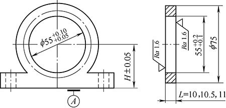
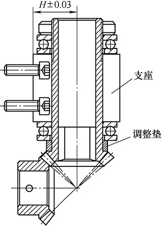
Firstly, the screw bearing is mapped. If it is directly processed according to the coupling size φ55mm, it will inevitably result in the processing of the bearing sleeve (only 2.5mm on one side) is too thin. Taking into account the strength of the parts and the difficulty of machining the spare parts, the hole was finally enlarged to φ65mm and then the sleeve was enlarged to increase the thickness of the single side to 5mm. At the same time, in order to ensure the coaxiality between the upper and lower bearing holes of the screw and the hole of the nut holder, firstly, a test rod not shorter than the length of the screw is processed, the silk bearing is preloaded, and then the inspection rod is inserted into the screw. , the lower bearing hole (the diameter of the inspection rod is slightly smaller than the screw holder hole 0.02mm), and the dial gauge on the test rod is hit in the inner hole of the silk bearing, slowly rotate the inspection rod, according to the detected value Adjust the height and the left and right position of the silk bearing, and adjust the appropriate adjusting gasket to make the coaxiality of the three bearings within 0.03mm. In order to ensure the spatial position of the bevel gear, the height dimension H of the center hole of the original bearing hole should be measured on the coordinate measuring instrument before the boring. When the boring is used, the machining is performed with the reference as the reference. The accuracy is satisfied (H±0.05). )mm. The gap of the bevel gear in the 90° direction can be tested by a set of adjusting washers of different thicknesses. The contact gap is measured by a meter. The method is to fix a gear, and the table is placed on the tooth surface of the mating gear. The difference between the paired gears and the read gear is the fitting gap value, and the indication value is less than 0.03 mm, as shown in Fig. 2. In the assembled state, the tool holder is moved, and the hand feel is flexible and there is no stagnation and dead point to verify the assembly gap state of the bevel gear. Through this method, the assembly precision of the lead screw is achieved at one time. By testing the parts, the processing quality is qualified, which greatly shortens the time for equipment failure and even the line stop.
Figure 2 Screw mounting diagram
2. Renovation and repair of the universal ball screw of XA 6132A/3
Universal lifting table milling machine XA6132A/3 on the processing line of the large wheel tow lifter shell. The machine tool was produced by Beijing No.1 Machine Tool Plant in 1987. It was specially designed to use a ball screw structure with high transmission precision. Although it can obtain high machining accuracy, it cannot be purchased after the damage. Screw spare parts can only be replaced by other lead screws. The shape structure of the original ball screw is shown in Figure 3, involving three length dimensions.
Figure 3 Ball screw structure diagram
Select the XA6132 lead screw of the approximate model. After comparison, it is found that the length structure and the diameter of each part of the common type of copper nut, screw and nut support are completely different. The existing screw structure is shown in Figure 4.
Figure 4 ordinary screw structure diagram
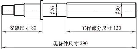
After on-site analysis, only the unconventional maintenance method can be used, and the transformation plan of cutting and connecting the two lead screws into one body is proposed. The front part of the original XA6132A/3 ball screw is left to ensure the length of the assembly part is 90mm, and it is connected with the trapezoidal thread 130mm working part of the spare part XA6132 screw to restore the transmission function.
When the XA6132 lead screw is actually cut off, it needs to be lengthened appropriately. At the same time, the interface diameter is processed by 20mm to ensure the concentricity with the shaft centerline is ≤0.05mm, and there is a 0.02mm interference when docking, so that the positioning is reliable. The structural effect after docking is shown in Figure 4. The outer ring is subjected to welding cooling correction, and finally the radial runout of the entire repair fitting is measured ≤ 0.05 mm.
During assembly, the copper nut support is pre-assembled on the bed body, and a test rod is made of the nominal size of the support hole. The inspection rod is inserted into the hole, and then the dial gauge is rotated to measure the relative deviation of the left-hand positioning bearing hole of the screw. According to the obtained value, the position of the repairing support is adjusted to satisfy 0.03 mm. Next, insert the silk nut into the hole of the bearing sleeve and fix it. After assembling the screw, bearing and gear, manually run the test. When the hand feels no stagnation, the last two pins are fixed. 5 is shown. The actual test equipment runs smoothly and the parts processing quality is qualified, which fully meets the production and process requirements.
Figure 5 Screw rod docking diagram
Through the practice description of the above two maintenance examples, in the actual maintenance work of the equipment system, the bottleneck equipment must not be limited by spare parts, unequal, not relying on, actively expand the ideas to carry out improvement work, in order to achieve the production cycle and processing quality the goal of.
references:
[1] Cheng Daxian. Mechanical Design Handbook [M]. 4th edition. Beijing: Chemical Industry Press, 2002.