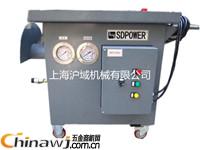
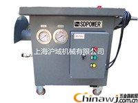
In the production process of high-speed wire and bar, the roller is one of the important components. Due to the production needs, when rolling different specifications of wire, it is necessary to replace the roller ring of the corresponding specification, and after rolling a certain tonnage of wire Because of the wear of the roller ring, it is also necessary to replace the roller ring of the corresponding specification. The hydraulic roll change trolley is a special equipment for high-speed wire and bar disassembly and assembly roll ring.
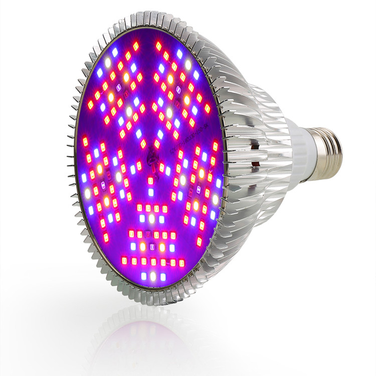
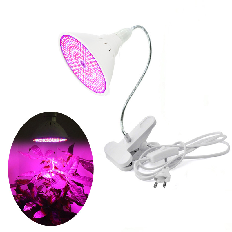
Plant Light Bulbs with E27/E26/G14 socket, E27 is normal, E26 G14 customzied, lamp with full spectrum lighting, each lamp can cover 0.8-1.2 square meter.
We can make any grow bulb you wanted, special bulb MOQ 500pcs, we are manufacturer, can offer you Best Grow Lights with lowest price.
Led Grow Light Bulbs,Grow Light Led Light Bulbs
I. Overview
Introduction of Hydraulic Roller Cars of Shanghai Huyu Machinery Co., Ltd.: Hydraulic Roller Cars are hydraulic control systems designed for high-speed wire and bar mills in the metallurgical industry. It is a special equipment for high-speed wire and bar disassembly and assembly roll ring.
The whole system consists of four parts: electric pump, valve block, mobile trolley and electronic control.
It generates hydraulic pressure from the system and acts on the roll changing tool (loading roller and unloading roller) to press or loosen the taper sleeve on the roller ring.
Second, the main technical parameters
High pressure:
700
Bar
High pressure flow:
1
L/min
Low pressure:
80
Bar
Low pressure flow:
3.5
L/min
Motor Power:
1.5
KW
Motor speed:
1500
r/min
Fuel tank capacity:
16
L
Dimensions (length × width × height):
1100×670×860
Mm
Third, the operation steps
First connect the 380V power supply (pay attention to the motor steering), confirm that the line sequence is connected correctly (it is best to open the electric control box with a voltmeter to measure whether the input voltage of the leakage switch is 220V), and then open the main power switch on the panel to the "ON" position. .
A mounting roller ring operation
1 low pressure plunger 2 high pressure plunger
Screw the loading tool onto the roll shaft so that the end face of the tool is as close as possible to the roll ring, and then pressurize the quick change joint.
1. Select the selector switch on the button box to the mounting position.
2. Press the install button. The system pressure roller is pressed to about 50 bar to position the roller ring. 2 At this time, continue to pressurize (the sleeve is pressed in) until the roller is low pressure to 150 bar, and the roller is pressurized to a pressure of about 550 bar. Each line factory can set the pressure value required to press the taper sleeve according to the process requirements.
3. See if the two pressures indicated on the pressure gauge have reached the specified values. When the high pressure gauge shows the set pressure value, continue to hold down the load roller button for a few seconds (depending on the process requirements).
4. Release the install button. The high pressure plunger 2 is immediately relieved of pressure, and the low pressure plunger 1 is released after a predetermined time (about 5 seconds). The action causes the high pressure plunger to retract. At this point the electric pump is also turned off together. Roller tool Low pressure piston is reset by spring. It is recommended that the roller loading operation be repeated once.
5. When the pump stops working, loosen the quick coupling of the tubing and separate the tool head from the hose.
B Disassembly roller ring operation
Fully fasten the disassembly roller head and the taper sleeve (the cone sleeve is in contact with the locating nut of the detachment roller head)
Note: The threaded sleeve of the female connector of the quick-change coupling is completely screwed in, and the end face is close to the male connector for the block-changing connection.
1. Select the selector switch on the button box to the removed position.
2. Press and hold the disassembly button and the working head begins to pressurize (the maximum pressure at which the taper sleeve is released is approximately 620 bar).
3. Release the disassembly button so that the working head will be retracted by the spring.
4. Disconnect the quick couplings at both ends of the tubing and separate the tool head from the hose.
C electric pump use
The electric pump for the hydraulic roll change trolley is composed of ABB motor, imported plunger pump and gear pump. The imported plunger pump and gear pump respectively provide the high and low pressure required for the disassembly roller to work. The electric pump has a maximum supply pressure of 700 bar. At a pressure of 700 bar, the flow rate is 1 L/min (ie high pressure flow). At 100 bar pressure, the flow rate can reach 3.5 L/min.
2, the special electric pump built-in liquid level switch, through the PLC, such as the electric pump when the oil breaks, the warning yellow light is on, and the hydraulic roll changing car stops working. Only after waiting for the fuel can you continue working. Since the pump is an oil-invasive electric pump, the hydraulic oil in the pump acts both as a pressure output and as a cooling. Under normal circumstances, the liquid level protection is set at about 60/% of the oil capacity. Sometimes the oil level shows oil, but the electric pump does not work, it is to protect the electric pump from being burned out.
3. Install a return filter on the right rear of the electric pump. The filter has a filter pressure gauge. When the gauge pointer points to the yellow area, the filter is about to be invalid and needs to be replaced. When the pointer points to the red area, stop using the car, otherwise it will cause damage to the electric pump.
D pressure relay setting
Loosen the cap or knob and adjust the bolt with a tool (screwdriver or wrench). The pressure is increased clockwise and the pressure is lowered counterclockwise.
IPH-3501E Pressure Relay IPH-7001E Pressure Relay
E Pressure change roller setting
Pressure gauge IPH-3501E pressure relay IPH-7001E pressure relay
9608 pressure reducing valve
23DFB-220 solenoid valve (normally closed No. 1) 23DFK-220 solenoid valve (normally opened on the 3rd)
23DFB-220 solenoid valve (normally closed on the 2nd)
The output pressure of the hydraulic re-roller is divided into two pressure systems: the loading roller and the unloading roller.
When the roller loading operation is selected, when the operating handle mounting button is pressed, the electric pump in the roller changing cart and the first solenoid valve are simultaneously activated. At this time, the system outputs a low pressure of the pressure roller ring, and when the low pressure reaches about 50 bar, the pressure is passed. The trigger of the relay activates the solenoid valve No. 2 to output the high pressure of the pressure taper sleeve. When the pressure reaches the set value (the pressure value is determined by the process requirements), continue to hold down the button for a few seconds and then release it. The high pressure disappears, and the system is turned off after the low pressure of the PLC control system in the system continues to run for 5 seconds (to retract the high pressure plunger of the loading tool), and the loading roller is completed.
Low pressure setting
9608 valve factory setting 160bar
Start system pressure setting DG34 pressure relay is 60~80bar
Roller high pressure setting MVP4AR overflow valve is 400bar
When the unloading roller operation is selected, since the unloading roller is separated by the taper sleeve and the roll shaft as the standard, and the system that requires separation is stopped to prevent the pressure from being continued after the separation, the unloading roller tool and the taper sleeve are smashed or damaged. In the detaching roller tool system, the above actions are completed by the pressure relay DG33 and PLC control.
The setting of the anti-roller protection pressure, the DG33 pressure relay is factory set to 200bar, and generally no adjustment is needed.
First, the precautions during operation
Power supply switch
Emergency stop loading/unloading roller loading roller button unloading roller button
Before the button is operated, you should look at whether the loading and unloading roller head is in place for the next step.
While operating the button, you should look at changes in system pressure to determine when to operate the button.
2.1 Loading the roller, when the high and low pressure of the roller reaches the set value at the same time, after releasing the pressure for several seconds, release the button to complete the roller.
(recommended to repeat the operation once)
Occasionally, when the low pressure of the loading roller is higher than the set value, the button needs to be released from the rising trend, and the roller loading operation is resumed.
When removing the roller, pay attention to the pressure gauge. When the pressure of the detaching roller rises to a certain value, the button should be released at the moment of falling back (the stop function has been set inside the trolley). At this time, the taper sleeve has been separated from the roller shaft, and the detaching roller is completed. .
Five, maintenance considerations
1, the hydraulic control system should be operated and maintained by professionals.
2, should be regularly inspected during use:
Check the control valve group of the pipeline and the fuel tank and accessories for leaks; check if the tank level is normal;
Whether the motor and hydraulic pump have abnormal noise and abnormal vibration; if an abnormality is found, it should be handled as soon as possible.
The leakage switch in the electric control box should be checked once a month. When the test button of the leakage switch is energized during the inspection, the description of the tripping can be performed well. Otherwise, the leakage switch is broken and needs to be replaced to ensure the safety of electricity. .
3, the quality of hydraulic oil should be checked regularly, usually once a year, after the hydraulic oil is degraded, the hydraulic oil must be replaced as soon as possible. It is recommended to use Mobil 32 or 46 anti-wear hydraulic oil.
4. Two alarm lights on the control panel panel. Once the alarm light is on, it should be handled by a professional as soon as possible.
When the liquid level abnormality alarm light is on, the system will perform the emergency shutdown by itself, and the maintenance personnel should immediately handle it.
The red light is on, the power is on; the green light is on, the system is running; the yellow light is on, the system stops working, and it needs to be refueled.
5. Once the pressure relay is set, non-professionals should not adjust it at will.
6, the use of tubing should ensure the bending radius, while avoiding the source of fire and hard objects to the tubing to avoid accidents.
7, to ensure that the block replacement connector should be cleaned and inserted every time it is used.
85% of the faults in the system are caused by the uncleaning of the hydraulic oil. Therefore, the hydraulic oil must be kept clean during the installation, use, maintenance and repair of the hydraulic system. This guarantees the performance of the hydraulic system and guarantees the hydraulic system. The normal use of reducing malfunctions is crucial!
When refueling, you must use a filter trolley!
Second, hydraulic car failure check steps
malfunction
possible reason
Method of exclusion
Roller/reel is high, low pressure and no pressure
The pump is not working properly
Check the PLC operation, AC contactor, and thermal protector in the electronic control section.
Pump relief valve does not work
Replace the relief valve or ask a professional maintenance engineer to inspect and repair
Leakage in the valve block
Reconnect solenoid valve, relief valve
Solenoid valve leakage
Replace the solenoid valve or ask a professional maintenance engineer to inspect and repair
Connecting pipe leak
Reconnect the pipeline
Pressure gauge damage
Replacement pressure gauge
The loading roller has a low pressure and the high pressure does not reach the set pressure.
Overflow valve pressure regulation is unstable
Replace the solenoid valve or ask the Shanghai company to detect and repair
There are no high and low pressure rollers, and the roller is normal.
1# solenoid valve leakage
Replace the solenoid valve or ask the Shanghai company to detect and repair
The pressure relief valve of the 9608 valve block is not decompressed
Reset the pressure or replace the pressure reducing valve.
0601 valve block relief valve does not work Reset the pressure or replace the relief valve.
The loading roller is normal and the roller is not normal.
3# solenoid valve leakage
Replace the solenoid valve or ask the Shanghai company to detect and repair
The loading roller has a low pressure and no high pressure.
IPH-7001E pressure relay failure
Reset the pressure or replace the IPH-7001E pressure relay.
Check if there is a signal from the pressure relay in the PLC
PLC controller failure
Rewrite the program or replace the PLC controller.
The pressure of the unloading roller is there, but the adjustment is up, and the pressure of the loading roller is equal.
3# solenoid valve leakage
Replace 3# solenoid valve 
Http://news.chinawj.com.cn  Editor: (Hardware Business Network Information Center) http://news.chinawj.com.cn


Horticultural Grow Bulb ,Led Grow Light Par,Indoor Grow Bulb,Indoor Plants Grow Bulb
Shenzhen Wenyi Lighting Technology Co., Ltd , https://www.szwenyigrow.com