Furniture Handle,Exterior Door Handle,Nordic Brushed Gold Handle,Space Aluminum Alloy Handle Guangzhou Junpai Hardware Co., Ltd , https://www.junpaihardware.com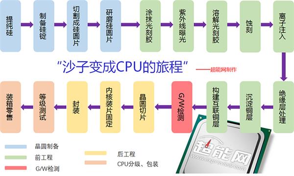
As the semiconductor material, the most used one is silicon. Its reserves in the elements on the surface of the earth are second only to oxygen, and the silicon content is 27.72%. Its main form is sand (the main component is silica), and the sand is inside. Contains a considerable amount of silicon. Therefore, silicon is most suitable as a raw material for IC production. Think about the vast expanse of desert on the earth. The source is cheap and convenient. 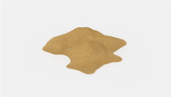
However, the actual purity of silicon used in the IC industry must be as high as 99.999999999%. At present, the silica is reduced to a purity of 98% of metallurgical grade elemental silicon by using silica and coking coal at 1600-1800 ° C, followed by purification of 99.99% of polycrystalline silicon using hydrogen chloride. Although the purity of silicon at this time is already high, the internal disordered crystal structure is not suitable for the fabrication of semiconductors, and further purification is required to form a single crystal silicon of a fixed uniform morphology. 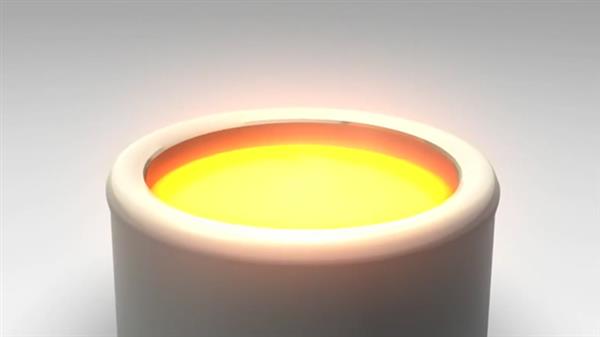
Single crystal means that the atom presents a regular ordered arrangement in three dimensions, while single crystal silicon has a "diamond structure", each unit cell contains 8 atoms, and its crystal structure is very stable. 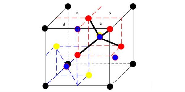
4, silicon ingot slices
The prepared single crystal silicon ingot was cut end by end, and its diameter was trimmed to the target diameter, and the silicon ingot was cut into a piece of uniform wafer (1 mm) using a diamond saw. Sometimes in order to determine the crystallographic orientation of the silicon wafer and to accommodate the handling needs of the IC fabrication process, an "orientation plane" or "gap" mark is cut at the edge of the silicon ingot. 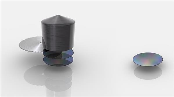
The surface of the cut wafer is still not smooth, and needs to be carefully ground to reduce the unevenness caused by the cutting. During the cleaning, the surface of the wafer is cleaned with a special chemical liquid, and finally polished and polished. Heat treatment is performed to form a "defect-free layer" on the surface of the silicon wafer. A piece of sparkling silicon wafer is thus produced and placed in a sealed package in a special fixed box. 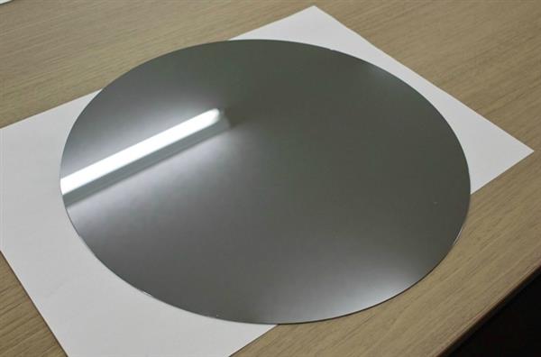
Pre-engineering - making chips with circuits
6, smearing photoresist
The silicon wafers that have been bought can be put into the production line after being inspected without damage. In the early stage, there may be various film forming processes, and then the photoresist is applied. The lithography process is a graphic photocopying technology and a key process in integrated circuit manufacturing processes. First, a photoresist (photosensitive resin) is dropped on a silicon wafer, uniformly applied as a photoresist film by high-speed rotation, and a photoresist film is cured at an appropriate temperature.
Photoresist is a material that is sensitive to light, temperature, and humidity. It can change chemical properties after illumination, which is the basis of the entire process. 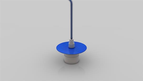
In terms of a single technical process, the lithography process is the most complex and costly. Because the lithography template, lens, and light source together determine the size of the transistor "printed" on the photoresist.
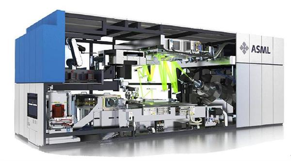
The photoresist-coated wafer is placed in an exposure apparatus of a step-and-repeat exposure machine to perform "copying" of the mask pattern. The mask has a pre-designed circuit pattern, and the ultraviolet light is refracted through the mask through a special lens to form a circuit pattern in the mask on the photoresist layer. Generally, the circuit pattern obtained on the wafer is 1/10, 1/5, 1/4 of the pattern on the mask, so the step-and-repeat exposure machine is also referred to as a "reduced projection exposure device". 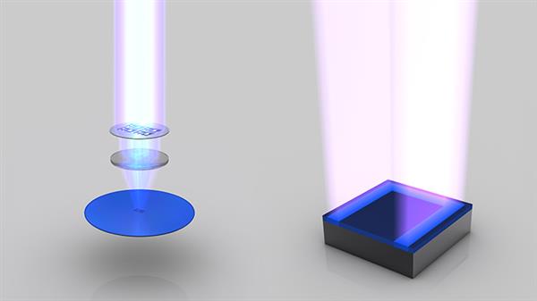
The exposed wafer is developed. Taking a positive photoresist as an example, after spraying a strong alkaline developing solution, a photoresist that is irradiated by ultraviolet light undergoes a chemical reaction, a chemical reaction occurs under the action of an alkali solution, and is dissolved in the developing solution without being irradiated. The photoresist pattern will remain intact. After development, the surface of the wafer is rinsed and sent to an oven for heat treatment to evaporate moisture and cure the photoresist. 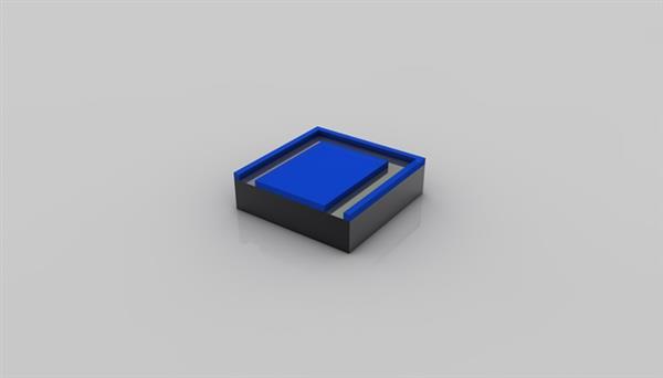
Immersing the wafer in a special etched trench containing the etchant dissolves the exposed portion of the wafer, while the remaining photoresist protects the portion that does not require etching. Ultrasonic vibration is applied during the acceleration to remove impurities adhering to the surface of the wafer to prevent the etching product from staying on the surface of the wafer to cause uneven etching. 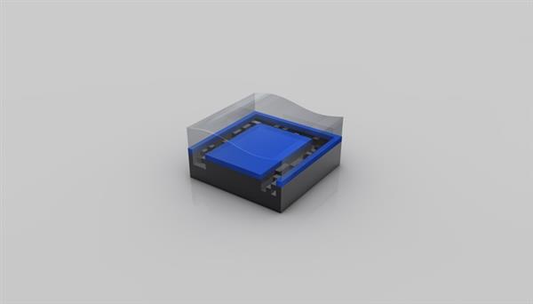
The photoresist is ashed by an oxygen plasma to remove all of the photoresist. At this point, the first layer of the designed circuit pattern can be completed. 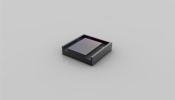
Since the current transistor has a 3D FinFET design, it is impossible to produce the desired pattern in one time. It is necessary to repeat steps 6-8 for processing, and various film forming processes (insulating film, metal film) are involved in the middle. Among them, the final 3D transistor is obtained. 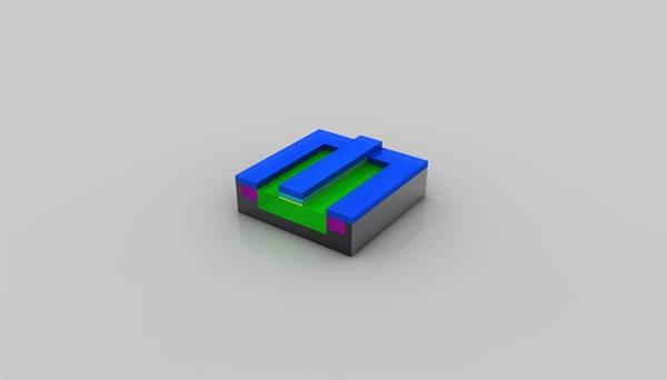
The process of consciously introducing specific impurities in a specific area is called "impurity diffusion." In addition to the conductivity type (P-junction, N-junction), impurity diffusion can also be used to control impurity concentration and distribution.
Ion implantation is generally used for impurity diffusion. In an ion implanter, conductive impurities to be doped are introduced into an arc chamber, ionized by discharge, and ions of tens to thousands of keV energy are accelerated after electric field acceleration. The beam is injected from the surface of the wafer. After the ion implantation, the wafer needs to be subjected to heat treatment. On the one hand, the thermal diffusion principle is used to further "press" the impurities into the silicon, and on the other hand, the lattice integrity is restored and the electrical characteristics of the impurities are activated. 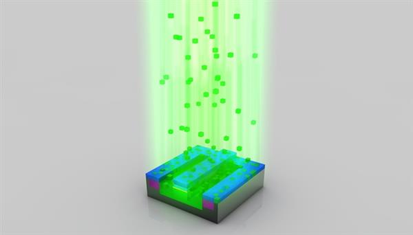
10, remove the photoresist again
After ion implantation is completed, the photoresist mask remaining by selective doping can be removed. At this time, a small portion of silicon atoms inside the single crystal silicon have been replaced with "impurity" elements, thereby producing free electrons or holes. 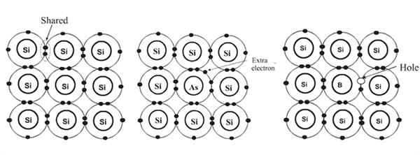
At this time, the prototype of the transistor has been substantially completed, and a silicon oxide film is completely deposited on the surface of the silicon wafer by vapor deposition to form an insulating layer. A photolithographic mask technique is also used to open a hole in the interlayer insulating film to extract the conductor electrode. 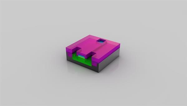
A copper layer for wiring is deposited on the entire surface of the wafer by a sputter deposition method, and the copper layer is further engraved using a photolithography mask technique to form a source, a drain, and a gate of the field effect transistor. Finally, an insulating layer is deposited on the entire surface of the wafer to protect the transistor. 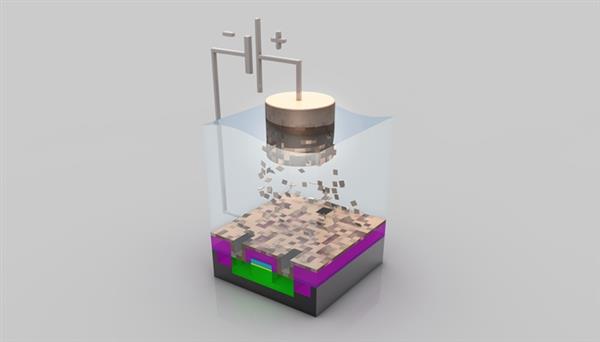
After a long process, billions of transistors have been fabricated. The rest is how to connect these transistors together. Similarly, a copper layer is formed first, and then a fine operation such as a photolithography mask, etching, and the like is performed, and then a lower copper layer is deposited. . . . . . Such a process is repeated a plurality of times depending on the size of the transistor and the degree of reproduction of the chip. The result is an extremely complex network of multilayer connection circuits. 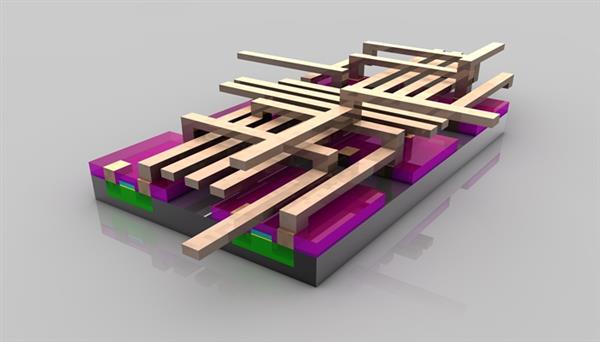
In addition, in order to successfully complete the multilayer Cu wiring, a new Damascus wiring method was developed. After the barrier metal layer was plated, the Cu film was sputtered as a whole, and the Cu and the barrier metal layer outside the wiring were removed by CMP. Required wiring. 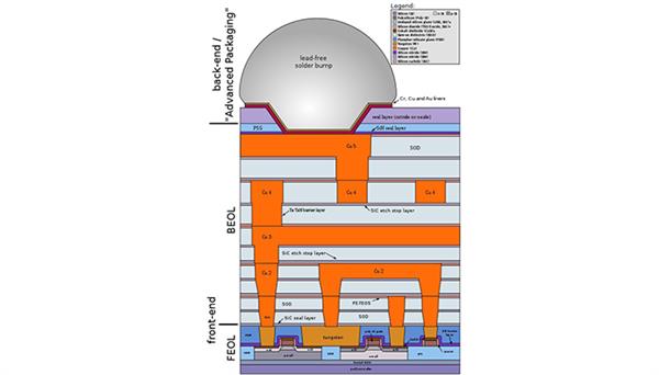
Post-engineering - from dicing to finished product sales 14, wafer level testing
Between the pre-engineering and the post-engineering, there is a Good-Chip/Wafer inspection project, referred to as G/W detection. The goal is to verify that each chip manufactured on each wafer is qualified. It is usually detected by using the probe in contact with the electrode pad of the IC, transmitting a pre-programmed input signal, and detecting whether the signal at the output of the IC is normal, thereby confirming whether the chip is qualified.
Due to the current redundancy design in IC manufacturing, even "failed" chips can be replaced with redundant units by using redundant units. Only lasers can be used to cut pre-designed fuses. Of course, the chip has serious problems that cannot be recovered and will be marked with discarded tags. 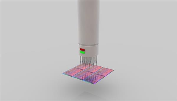
After the IC core is fabricated on the wafer and passed the test, it enters the dicing stage. The dicing knife used for dicing is a very thin wafer knife to which diamond particles are adhered, and its thickness is only 1/3 of that of human hair. Each IC chip on the wafer is cut down to form a core Die.
After the rupture is completed, the chip will be visually inspected. If there are damages and scars, it will be discarded. The defects found in the previous G/W inspection will also be removed. 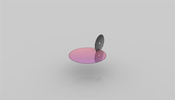
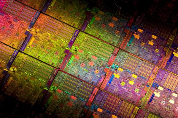
After the chip is tested, it can only be regarded as a semi-finished product because it cannot be used directly by consumers. It is also necessary to mount the core assembly to the substrate circuit after the loading operation. The entire operation of the loading operation is performed by the computer-controlled automatic die bonding machine. 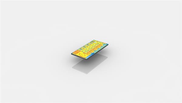
The loading operation only completes the fixing of the chip, and the electrical connection has not yet been made, so it is also required to be combined with the contacts on the package substrate. Flip-chip forms are now commonly used, with the contacts facing down, and bumps are pre-formed with solder so that the bumps align with the corresponding pads and are joined by thermal reflow or ultrasonic bonding.
The package can also be said to be a housing for mounting a semiconductor integrated circuit chip, which not only functions to mount, fix, seal, protect the chip, but also enhances the thermal conductivity. At present, Intel has adopted LGA package in recent years. After the core is connected with the contact on the package substrate, the core is coated with thermal grease or filled with brazing material, and finally the metal casing is packaged to increase the core heat dissipation area and protect the chip from the chip. Directly squeezed by the radiator.
At this point, a complete CPU processor was born. 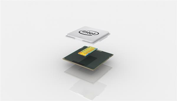
After the CPU is manufactured, a comprehensive test will be performed. Test the stable frequency, power consumption and heat of each chip. If there are hardware defects inside the chip, hardware shielding measures will be taken, so different levels of CPUs, such as Core i7, i5, and i3, are divided. 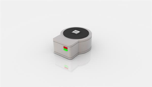
After the CPU completes the final leveling test, it will be packaged in boxes and enter the OEM, retail and other channels. 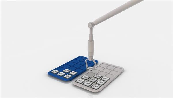
At least a billion yuan of investment in a complete and most advanced CPU production line, and the largest part of it is the lithography machine, mask, film forming machine and diffusion equipment in the former project, accounting for 70% of the total investment. It is the most sophisticated instrument in the world, and each one is worth a lot. As a reference, CPU plant construction, auxiliary equipment, and clean room construction costs account for 20%.
I don't know if you see this here. I think that at least a few hundred pieces can buy a CPU that converges the wisdom of human wisdom. Is it worth it? And the small partners of China Superhard Materials Network, how many superhard material tools have you found in the process of making “sand to CPU�
Why is the CPU made of sand so expensive? The hero behind the scene is actually a super hard tool
Abstract In general, our understanding of IC chips is limited to its concept, but how does it come to IC chips that have been applied to a wide variety of digital products? You may only know that the silicon used to make the IC chip comes from sand, but why does the CPU made of sand sell it...
In general, our understanding of IC chips is limited to its concept, but how does it come to IC chips that have been applied to a wide variety of digital products? You may only know that the silicon used to make the IC chip comes from sand, but why is the CPU made of sand so expensive? The following will use the common Intel, AMD CPU as an example to describe the brief production process of sand to CPU. I hope that everyone has a general understanding of the CPU production process, and how to sell the CPU so expensive! Production of silicon wafers
1. An important source of silicon: sand "Diamond" structure of single crystal silicon
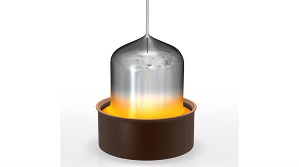
Usually, single crystal silicon ingots are prepared by the Czochralski method. A seed crystal is added to the silicon still in liquid state to provide the center of crystal growth. With proper temperature control, the crystal is slowly lifted up and gradually increased. Pulling speed, rising while rotating around the lifting shaft at a certain speed to control the silicon ingot within the required diameter. At the end, as long as the temperature of the single crystal silicon furnace is raised, the silicon ingot will automatically form a tapered tail, and the preparation is completed, and more IC chips are produced at one time. Finished silicon wafer
Usually, semiconductor IC manufacturers do not produce such wafers themselves, and usually purchase them directly from silicon wafer factories for subsequent production. The most advanced ASML company TWINSCAN NXE: 3300B
8. Dissolve part of the photoresist Left: silicon atom structure; medium: doped arsenic, more free electrons; right: doped with boron, forming electron holes
11, insulation treatment Damascus method multilayer wiring
The chip circuit has been basically completed, and it has undergone hundreds of different processes, all of which are based on refinement operations. Any single place error will cause the entire wafer to be scrapped, and the number will be fabricated on more than 100 square millimeters of wafers. One billion transistors are the crystallization of all the wisdom of mankind since civilization. Unsplitting one CPU core
16, loading